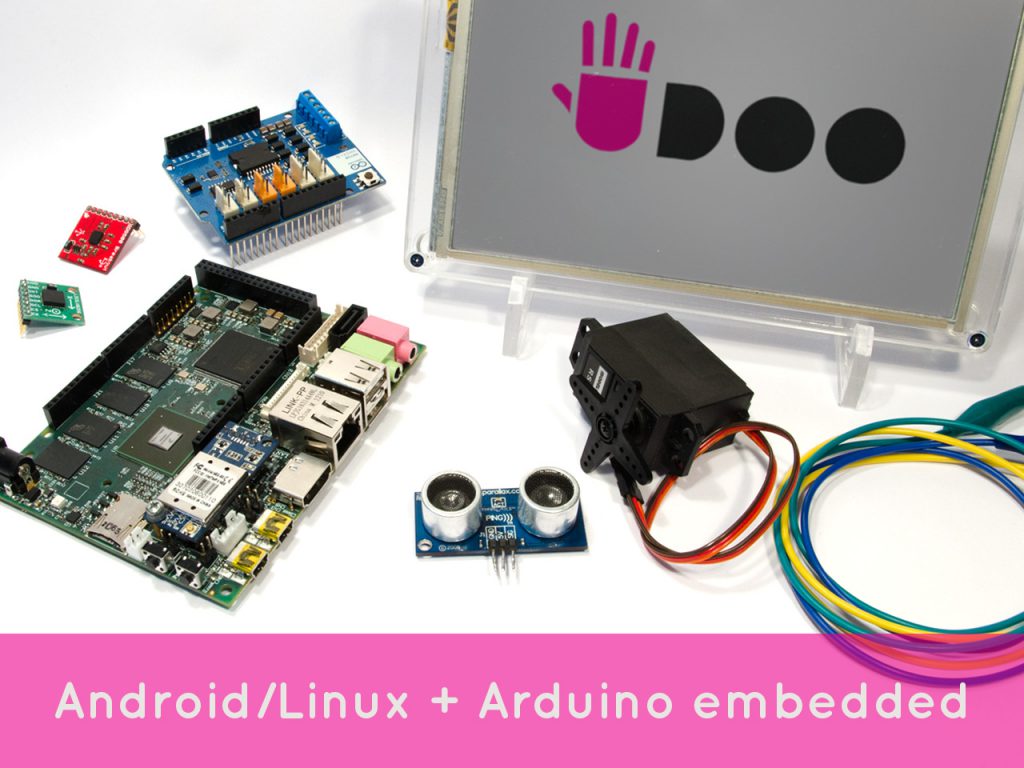
UDOO is a multi development platform solution for Android, Linux, Arduino and Google ADK 2012.
UDOO allows you to switch between Linux and Android in a few seconds,
simply by replacing the Micro SD card and rebooting the system. UDOO is a stand alone computer itself and since is based on the
Freescale i.MX 6 CPU, it runs an optimized version of Linux Ubuntu for
ARM architecture, called Linaro (11.10 at the moment). Linaro
environment has everything you need for programming, for example you can
use the Arduino IDE to build & upload your sketches to the
Arduino-compatible embedded board, without additional/external cable
connections.
Android 4.2.2 Jelly Bean runs smootly on UDOO giving you all the features of an Android device. And UDOO is compatible with all the sketches, tutorials and resources
available on the Arduino community as well as all the shields, sensors
and actuators for Arduino DUE available on the market.
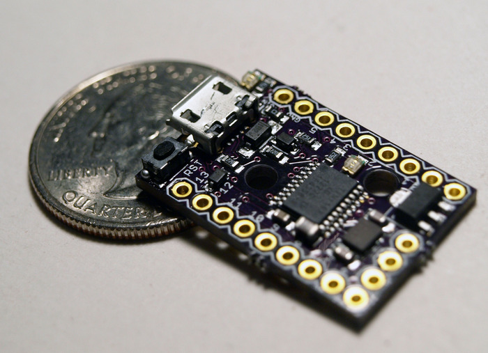
The tiny Arduino IDE ready, usb and mobile dev board
and ecosystem - cheap enough to leave in any project! Wi-fi, BLE, and
25+ shields!
Serial over USB debugging, USB programmable, 14 i/o, SPI,
I2C, UART, USB Device Emulation, Mobile Development Ready, Optional BT,
BLE, Mesh, and Wi-Fi.
The super small, dirt cheap,
always open source, Arduino compatible, USB (and Mobile and Wireless!)
development (and production) platform, and follow-up to the original
Digispark.
Easier to use, more pins, more program
space, more features, more reliable - supporting the entire existing
Digispark ecosystem of 25+ shields and adding Wi-Fi, Bluetooth, BLE
shields and more! Ready for all your projects - including mobile
hardware development! All still super affordable!
The
Digispark Pro Ecosystem is the cheapest, Arduino compatible development
platform for Mobile and Wireless hardware development.
Compatible with Arduino IDE 1.5 (OSX/Win/Linux)
Fully signed drivers and executable for easy installation
USB programming, USB device emulation, USB-CDC virtual serial port emulation
16 Mhz AVR MCU - using a true 16Mhz precision crystal
16KB Flash Memory (14.5K+ after bootloader)
Serial over USB debugging and communication!
14 i/o Pins (2 shared with USB)
I2C, true SPI, UART, LIN, and USI
ADC on 10 pins
3 PWM Channels (which can be assigned to a selection of pins)
Power via USB, or External Source - 5v or 6-16v (automatic selection)
On-board button that can be used as a reset, program, or user button - or can be disabled to use that pin as general i/o - without changing the bootloader
On-board 500ma 5V regulator
Power LED and Test/Status LED (on Pin 1)
User accessible solder jumpers to disable LEDs, and other features for lower power consumption
Two mounting holes.
Breadboard compatible pin out/spacing (the three side header pins are only for legacy shield support).
Wi-Fi, Bluetooth, BLE, Mesh shields: The Digispark Pro is
backwards compatible with all existing Digispark shields - and it has
some shields exclusive for the Pro including: a Wi-Fi shield, a
Bluetooth Classic shield, a Bluetooth 4.0/Low Energy Shield, and a
nRF24L01+ low cost mesh networking shield. These low cost shields
make the Digispark Pro the cheapest way to jump into Internet of Things,
Mobile, and Wireless development!
Not to be outflanked by rivals, Intel has released the $99
Minnowboard Max, a tiny single-board computer that runs Linux and
Android. It is completely open source – you can check out the firmware and software here – and runs a 1.91GHz Atom E3845 processor.
The board’s schematics are also available for download and the Intel
graphics chipset has open-source drivers so hackers can have their way
with the board. While it doesn’t compete directly with the Raspberry Pi –
the Pi is more an educational tool and already has a robust ecosystem –
it is a way for DIYers to mess around in x86 architected systems as
well as save a bit of cash. The system uses break-out boards called
Lures to expand functionality.
Intel is interested in this space mostly because it has been out of
it for so long. Raspberry Pi runs a Broadcomm system-on-chip with a
700Mhz ARM processor and is probably one of the most popular SBCs
available. The Minnowboard brings Intel’s low-power Atom processor back
into the hands of hackers and makes Intel relevant in that space again –
at least that’s the goal.
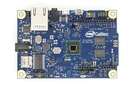
Intel Galileo development board is first product in a new family of
Arduino-compatible development boards featuring Intel architecture.
The platform is easy to use for new designers and for those looking to
take designs to the next level.
To create the Intel Galileo development board, Intel and Arduino have come together in a collaboration to push the boundaries of technology, innovation, and creativity.
Intel Galileo is the first in a line of Arduino-certified development boards based on Intel x86 architecture and is designed for the maker and education communities.
Intel Galileo combines Intel technology with support for Arduino
ready-made hardware expansion cards (called "shields") and the Arduino
software development environment and libraries. The development board runs an open source Linux operating system with
the Arduino software libraries, enabling re-use of existing software,
called "sketches". Intel Galileo can be programmed through OS X,
Microsoft Windows and Linux host operating software. The board is also
designed to be hardware and software compatible with the Arduino shield
ecosystem.
Intel Galileo features the Intel Quark SoC X1000, the first product from the Intel Quark
technology family of low-power, small-core products. Intel Quark
represents Intel's attempt to compete within markets such as the Internet of Things.
Features
400MHz 32-bit Intel® Pentium instruction set architecture (ISA)-compatible processor o 16 KBytes on-die L1 cache
512 KBytes of on-die embedded SRAM
Simple to program: Single thread, single core, constant speed
ACPI compatible CPU sleep states supported
An integrated Real Time Clock (RTC), with an optional 3V “coin cell” battery for operation between turn on cycles.
10/100 Ethernet connector
Full PCI Express* mini-card slot, with PCIe 2.0 compliant features
Works with half mini-PCIe cards with optional converter plate
Provides USB 2.0 Host Port at mini-PCIe connector
USB 2.0 Host connector
Support up to 128 USB end point devices
USB Device connector, used for programming
Beyond just a programming port - a fully compliant USB 2.0 Device controller
10-pin Standard JTAG header for debugging
Reboot button to reboot the processor
Reset button to reset the sketch and any attached shields
Storage options:
Default - 8 MByte Legacy SPI Flash
main purpose is to store the firmware (or bootloader) and the latest
sketch. Between 256KByte and 512KByte is dedicated for sketch storage.
The download will happen automatically from the development PC, so no
action is required unless there is an upgrade that is being added to the
firmware.
Default 512 KByte embedded SRAM, enabled by the firmware by default. No action required to use this feature.
Default 256 MByte DRAM, enabled by the firmware by default.
Optional micro SD card offers up to 32GByte of storage
USB storage works with any USB 2.0 compatible drive
11 KByte EEPROM can be programmed via the EEPROM library.
Imagine having a HD TV
that is 80 inches wide and less than a quarter-inch thick and can be rolled up when
you're not using it. What if you could have a display in your
car? How about a display monitor built into your clothing? These
devices may be possible in the near future with the help of a technology
called organic light-emitting diodes (OLEDs).
OLEDs are solid-state devices composed of thin films of organic molecules that create light with the application of electricity.
Structure of OLEDs
Like an LED, an OLED is a solid-state semiconductor device. They have either two layers or three layers of organic material; in the
latter design, the third layer helps transport electrons from the
cathode to the emissive layer.
By flow of electrons from cathode to anode, and holes the other way due to emissive and conductive organic layer the charges recombine to produce light. Emissive layer is responsible for light emission.
Foldable OLED
Foldable OLEDs have substrates made of very
flexible metallic foils or plastics. Foldable OLEDs are very lightweight
and durable. Their use in devices such as cell phones and PDAs can
reduce breakage, a major cause for return or repair. Potentially,
foldable OLED displays can be attached to fabrics to create "smart"
clothing, such as outdoor survival clothing with an integrated computer
chip, cell phone, GPS receiver and OLED display sewn into it.
Some more facts of OLEDs
OLEDs have large fields of view, about 170 degrees.
Because LCDs work by blocking light, they have an inherent viewing
obstacle from certain angles. OLEDs produce their own light, so they
have a much wider viewing range.
Lifetime - While red and green OLED films have longer
lifetimes (46,000 to 230,000 hours), blue organics currently have much
shorter lifetimes (up to around 14,000 hours[source: OLED-Info.com]).
Both Samsung and LG began flexible OLED mass production. Samsung is
making a 5.7" Full-HD panels while LG is making 6" 720p ones.
The Galaxy Round is the world's first device with a flexible OLED - it
has a 5.7" Full-HD curved display, based on a plastic substrate
LG Electronics introduced their 2014 TV lineup in Korea - unveiling a
total of 68 new models. The company will launch 77", 65" and 55" OLED TVs
- some of which will feature 4K UHD resolution. The company did not yet
announce prices and availability, but they did say that they will start
releasing the new TVs in key markets later this month.
Faster refresh rate, better contrast and better color reproduction.
DesignSpark PCB is the world’s most accessible electronics design
software. Easy to easy to learn and easy to use, DesignSpark PCB is
designed to significantly reduce your concept-to-production time. At the
core of this unique approach is a powerful software engine that enables
you to capture Schematics, design PCB boards and layouts. DesignSpark
PCB had won multiple awards and with over 250,000 registered users it
emerges as an electronic industry's standard for collaboration and file
sharing!
World’s first truly FREE and unrestricted electronics design software.
Developed by RS Components/Allied Electronics to enable engineers
rapidly design great products, DesignSpark PCB had won multiple awards
since 2010 while attracting over 250,000 activations. This breakthrough
in accessibility, backed by powerful features enabled engineers to share
designs within teams and externally - bringing collaborative hardware
design to a whole new level. http://www.designspark.com/eng/knowledge-item/designspark-pcb-product-brochure Download LINK: http://pcb.designspark.info/DesignSparkPCB_v6.exe
Want to know more? See a high level overview of the core functionality of DesignSpark PCB:
Take big ideas to the cloud with TI's Tiva™ C Series Connected LaunchPad, the first IoT-capable LaunchPad by TI
Quickly connect to the Internet with easy-to-use, evaluation tool based on Tiva TM4C1294 MCU with integrated Ethernet MAC+PHY
Features
TM4C1294NCPDT MCU: 120MHz 32-bit ARM Cortex-M4 CPU with floating
point, 1MB Flash, 256KB SRAM, 6KB EEPROM, Integrated 10/100 Ethernet
MAC+PHY, data protection hardware, 8x 32-bit timers, dual 12-bit 2MSPS
ADCs, motion control PWMs, USB H/D/O, and many additional serial
communication interfaces
Your Connected LaunchPad includes the following features: • Tiva TM4C1294NCPDTI microcontroller • Ethernet connectivity with fully integrated 10/100 Ethernet MAC and PHY Motion Control PWM • USB 2.0 Micro A/B connector • 4 user LEDs • 2 user buttons • 1 independent hibernate wake switch • 1 independent microcontroller reset switch • Jumper for selecting power source: – ICDI USB – USB Device – BoosterPack • Preloaded Internet-of-Things Exosite quickstart application • I/O brought to board edge for breadboard expansion • Two independent BoosterPack XL standard connectors featuring stackable headers to maximize expansion through BoosterPack ecosystem
Some more Details:
Microcontroller
The
TM4C1294NCPDTI is a 32-bit ARM Cortex-M4F based microcontroller with
1024-kB Flash memory, 256-kB SRAM, 6-kB EEPROM, and 120 MHz operation;
integrated 10/100 Ethernet MAC and PHY; integrated USB 2.0 connectivity
with external high-speed USB 3.0 PHY capability; a hibernation module, a
multitude of serial connectivity and motion control PWM; as well as a
wide range of other peripherals.
Ethernet Connectivity
The
Connected LaunchPad is designed to connect directly to an Ethernet
network using RJ45 style connectors. The microcontroller contains a
fully integrated Ethernet MAC and PHY.
Tool Options
• Keil ARM RealView® Microcontroller Development System • IAR Embedded Workbench for ARM • Sourcery Codebench • Generic GNU C Compiler • Texas Instruments' Code Composer Studio™ IDE
 All in One
 UDOO allows you to switch between Linux and Android in a few seconds,
simply by replacing the Micro SD card and rebooting the system. UDOO is a stand alone computer itself and since is based on the
Freescale i.MX 6 CPU, it runs an optimized version of Linux Ubuntu for
ARM architecture, called Linaro (11.10 at the moment). Linaro
environment has everything you need for programming, for example you can
use the Arduino IDE to build & upload your sketches to the
Arduino-compatible embedded board, without additional/external cable
connections.
UDOO allows you to switch between Linux and Android in a few seconds,
simply by replacing the Micro SD card and rebooting the system. UDOO is a stand alone computer itself and since is based on the
Freescale i.MX 6 CPU, it runs an optimized version of Linux Ubuntu for
ARM architecture, called Linaro (11.10 at the moment). Linaro
environment has everything you need for programming, for example you can
use the Arduino IDE to build & upload your sketches to the
Arduino-compatible embedded board, without additional/external cable
connections.