 Intel Galileo development board is first product in a new family of
Arduino-compatible development boards featuring Intel architecture.
The platform is easy to use for new designers and for those looking to
take designs to the next level.
Intel Galileo development board is first product in a new family of
Arduino-compatible development boards featuring Intel architecture.
The platform is easy to use for new designers and for those looking to
take designs to the next level.
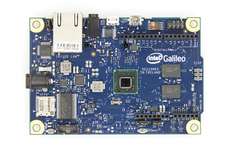
To create the Intel Galileo development board, Intel and Arduino have come together in a collaboration to push the boundaries of technology, innovation, and creativity.
Intel Galileo is the first in a line of Arduino-certified development boards based on Intel x86 architecture and is designed for the maker and education communities.
 Intel Galileo combines Intel technology with support for Arduino
ready-made hardware expansion cards (called "shields") and the Arduino
software development environment and libraries. The development board runs an open source Linux operating system with
the Arduino software libraries, enabling re-use of existing software,
called "sketches". Intel Galileo can be programmed through OS X,
Microsoft Windows and Linux host operating software. The board is also
designed to be hardware and software compatible with the Arduino shield
ecosystem.
Intel Galileo combines Intel technology with support for Arduino
ready-made hardware expansion cards (called "shields") and the Arduino
software development environment and libraries. The development board runs an open source Linux operating system with
the Arduino software libraries, enabling re-use of existing software,
called "sketches". Intel Galileo can be programmed through OS X,
Microsoft Windows and Linux host operating software. The board is also
designed to be hardware and software compatible with the Arduino shield
ecosystem.
Intel Galileo features the Intel Quark SoC X1000, the first product from the Intel Quark
technology family of low-power, small-core products. Intel Quark
represents Intel's attempt to compete within markets such as the Internet of Things.

Features
- 400MHz 32-bit Intel® Pentium instruction set architecture (ISA)-compatible processor o 16 KBytes on-die L1 cache
- 512 KBytes of on-die embedded SRAM
- Simple to program: Single thread, single core, constant speed
- ACPI compatible CPU sleep states supported
- An integrated Real Time Clock (RTC), with an optional 3V “coin cell” battery for operation between turn on cycles.
- 10/100 Ethernet connector
- Full PCI Express* mini-card slot, with PCIe 2.0 compliant features
- Works with half mini-PCIe cards with optional converter plate
- Provides USB 2.0 Host Port at mini-PCIe connector
- USB 2.0 Host connector
- Support up to 128 USB end point devices
- USB Device connector, used for programming
- Beyond just a programming port - a fully compliant USB 2.0 Device controller
- 10-pin Standard JTAG header for debugging
- Reboot button to reboot the processor
- Reset button to reset the sketch and any attached shields
- Storage options:
- Default - 8 MByte Legacy SPI Flash main purpose is to store the firmware (or bootloader) and the latest sketch. Between 256KByte and 512KByte is dedicated for sketch storage. The download will happen automatically from the development PC, so no action is required unless there is an upgrade that is being added to the firmware.
- Default 512 KByte embedded SRAM, enabled by the firmware by default. No action required to use this feature.
- Default 256 MByte DRAM, enabled by the firmware by default.
- Optional micro SD card offers up to 32GByte of storage
- USB storage works with any USB 2.0 compatible drive
- 11 KByte EEPROM can be programmed via the EEPROM library.
No comments:
Post a Comment